Harp Current Driver
Introduction
The Harp Current Driver is a Harp Standard device developed at the Champalimaud Foundation. It is a two channel, software programmable precision current source designed to drive LEDs with currents up to 500 mA per channel.
Its main application is optogenetic stimulation, either by directly driving the current of a high-power LED connected to one of its LED outputs, or by controlling an external LED driver through the device's analog voltage outputs. Besides constant currents, the device can generate pulse trains and ramps between different current/voltage values, so that typical stimulation protocols can be executed by the device itself, without timing jitter introduced by the computer. Although designed with optogenetics in mind, the device can be used in any application that requires a precise current drive, such as controlling electromagnetic brakes.
As with every Harp device, all events are time-stamped by the device and synchronized with the remaining Harp devices of the rig, and the digital inputs and outputs can be used to align the stimulation with other non-Harp events of the experiment.
Architecture
Each one of the two channels is built around a 16-bit DAC that sets the output of the channel. The same DAC is shared by the channel's LED output (a current sink) and by its DAC output (an analog voltage output), so each channel is operated either as a current source or as a voltage source.
The LED output is a classical op-amp/MOSFET voltage-to-current converter:
- a 16-bit DAC referenced to a buffered precision reference, sets the target voltage;
- a precision CMOS op-amp drives the gate of a logic-level N-channel power MOSFET mounted on a solderable SMT heatsink;
- the MOSFET source sits on a precise sense network whose voltage is sensed and fed back to the op-amp.
Negative feedback forces the voltage across the sense network to track the DAC voltage, so the output current is set only by the DAC and the sense resistance and is largely independent of the MOSFET characteristics, of its temperature and of the LED forward voltage, as long as the supply leaves enough headroom for regulation. The full scale is 500 mA with a resolution of ~15 µA per step.
The LED is connected between the positive supply rail (9–12 V) and the channel's LED output, so the device works as a ground-referenced current sink. A fixed-threshold thermostat, thermally coupled to the MOSFET, provides a hardware over-temperature shutdown that disables the output independently of the firmware.
Mode of Operation
At power-up both LED drivers are enabled with a set point of 0 mA, and the DAC outputs are at 0 V. The output of each channel is controlled by software:
- Current mode: writing a value in mA to
Led0Current/Led1Currentimmediately updates the current through the corresponding LED output. - Voltage mode: writing a value in mV to
Dac0Voltage/Dac1Voltageupdates the corresponding DAC output, which can be used, for example, as the analog input of an external LED driver. - Enable/disable: each LED driver can be switched off and on through the
LedEnable,LedDisableandLedStateregisters, without changing the configured set point.
Two functions can be applied on top of the configured value of each channel:
- Pulses: when enabled through
PulseEnable, the channel output alternates between the configured value and zero, with a programmable frequency and duty cycle. - Ramps: when configured through
RampConfig, transitions between different values are performed linearly over a programmable time, on rising and/or falling transitions. Ramps are only applied while the pulse function of that channel is off.
The two digital inputs report every transition through the DigitalInputState event, which can be
used to align the stimulation with external triggers. The two digital outputs are controlled by
software and can be used to drive external hardware from the same time base.
Key Features
- Two Independent Channels: each with a current sink LED output and an analog voltage output
- Precision Current Output: 0–500 mA per channel, 16-bit DAC with a ~15 µA step
- High Accuracy: ±0.14 % of reading ± 44 µA (typical, 25 °C), without calibration
- Analog Voltage Output: 0–5 V per channel, to control external LED drivers
- Pulses and Ramps: pulse trains with programmable frequency and duty cycle, and linear ramps on rising and/or falling transitions, generated by the device
- Thermal Protection: hardware over-temperature shutdown, independent of the firmware
- Harp Time-stamping: every event is time-stamped by the device and synchronized with the remaining Harp devices of the rig
- Digital IO: 2x digital inputs and 2x digital outputs for synchronization with external hardware
Connectivity
- State LED [STATE]: Green LED Harp status indicator
- LED Outputs [LED0, LED1]: 2x screw terminals, current sink up to 500 mA each
- DAC Outputs [DAC0, DAC1]: 2x screw terminals, 0–5 V analog outputs (16-bit)
- Digital IN/OUT [IN/OUT]: screw terminals for 2x digital inputs and 2x digital outputs (5 V)
- Clock Sync Input [CLKIN]: 1x Stereo jack clock input
- Computer Interface [USB]: 1x USB Type-B
- Power Supply [POWER]: 1x barrel connector jack, 9–12 V DC
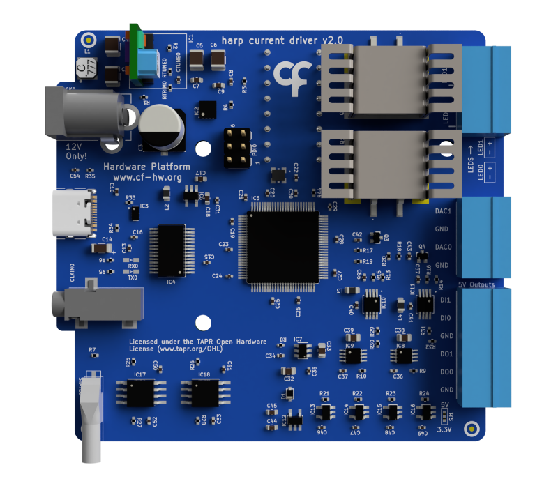

Technical Specifications
| Parameter | Specification |
|---|---|
| Channels | 2x (LED output + DAC output each) |
| LED Output Current | 0–500 mA per channel (current sink) |
| LED Current Resolution | ~15 µA (16-bit DAC, 15-bit range used) |
| LED Current Accuracy | ±0.14 % of reading ± 44 µA (typical, 25 °C) |
| DAC Output Voltage | 0–5 V per channel (16-bit) |
| Pulse Frequency | 1–255 Hz, 1 ms resolution |
| Pulse Duty Cycle | 1–100 % |
| Ramp Time | 1–65535 ms |
| Thermal Protection | Hardware shutdown at PCB temperature of 75ºC |
| Digital Inputs | 2x (5 V) |
| Digital Outputs | 2x (5 V) |
| Computer Interface | USB |
| Power Supply | 9–12 V DC |
The current that is not dropped on the LED is dissipated by the channel's MOSFET. The worst case happens at full current with a 12 V supply and a low forward voltage load (≈ 4.8 W per channel for an IR LED with VF ≈ 1.2 V at 500 mA). Whenever possible, use the 9 V supply option, or a supply voltage just above the forward voltage of the LED, to reduce the dissipated power. A short circuited load at 12 V is protected by the hardware thermal shutdown.